⚠️ Active Development - This project is currently in the design and prototyping phase. The approach described here is based on research and early testing, but has not yet been validated on a production vehicle. Hardware designs, wiring, and firmware are subject to change. Follow along, contribute ideas, but don't wire anything into your car based on this alone. Updates will be posted as the build progresses.
https://makeitbreakitfixit.com/2026/05/11/carcloak-taking-my-tesla-fully-offline-part-1/
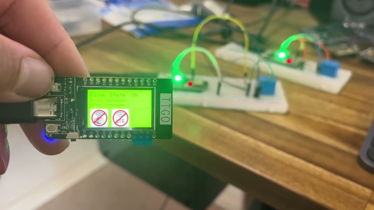
Watch the v1 prototype in action: BLE master/slave units controlling RF relay switching.
Welcome to the CarCloak Project, designed to empower Tesla electric vehicle owners with control over their car's internet connectivity. This repository contains the latest code and resources to implement a minimally intrusive solution for enhancing privacy.
CarCloak allows Tesla owners to take control of their car's internet access. Currently, Tesla vehicles are always connected to either WiFi or LTE, which raises privacy concerns for some users. With CarCloak, a physical button is used to disconnect the WiFi and LTE antennas, effectively taking the car offline. Pressing the button again restores the original internet connectivity settings.
This solution is designed to be minimally invasive, ensuring the installation can be fully reversed without causing any damage to the car.
- Privacy Control: A simple mechanism to toggle internet connectivity on or off.
- Non-Intrusive Design: Fully reversible installation process.
- Quick Recovery: The system quickly recovers from dropouts or failures by implementing retry mechanisms and ensuring consistent reconnection attempts.
- Optimised Debugging: Includes serial monitoring debug messages for efficient troubleshooting, along with useful messages shown on the units display.
For most Tesla Model 3 and Model Y vehicles, the antenna wires can be accessed in a non-destructive way. The setup involves two slave units, one located in each front door, that control the WiFi and LTE antennas. Here's how it functions:
-
Slave Units and Relays:
- The two WiFi and LTE antenna wires are unplugged and routed through the slave units.
- Each slave unit uses a relay switch to control whether the antennas are connected or disconnected.
- By default, the relays keep the antennas connected; if there is no power to the slave units, the antennas remain connected (this can be modified by altering the circuit).
-
Communication Between Units:
- The slave units are controlled by an ESP32 device (recommended ESP32-C3, but any BLE-supported ESP32 will work).
- These units use Bluetooth Low Energy (BLE) to communicate with a master unit.
-
Master Unit with Display:
- The master unit is an ESP32 TTGO T-Display with a built-in screen and buttons.
- The display shows the connection status of the slave units and provides troubleshooting information.
- It also displays the current state of the relays (connected or disconnected).
-
User Interaction:
- Pressing the button on the master unit toggles the relay states, effectively disconnecting or reconnecting the antennas.
-
Reliability Features:
- The code includes retry mechanisms to search for and reconnect any dropped slave units.
- It sends periodic messages to maintain the current state and employs an acknowledgment (ACK) system to confirm command receipt.
CarCloak is compatible with most Tesla Model 3 and Model Y vehicles.
For 2024+ Model 3 (Highland) vehicles, the architecture is different. The TCU Gen II integrates the LTE/5G modem, Wi-Fi, Bluetooth, and antennas in a single sealed unit with no external RF pigtails. The Highland approach uses an inline device on the 1000BASE-T1 Ethernet link between the TCU and MCU rather than switching antenna feeds directly. See the build log for full details.
Detailed writeup of the research, design decisions, dead-ends, and progress is documented at makeitbreakitfixit.com. The blog covers the Highland-specific architecture findings, Ethernet cut approach, parts selection, and bench test setup.
Ensure you have the following installed:
- Arduino IDE (latest version recommended)
- ESP32 Development Board
- Necessary tools for installation and testing
- Moderate electronics knowledge, including soldering
- Moderate coding knowledge in C++
- 2x ESP32-C3 for the slave units
- 1x ESP32 TTGO T-Display for the master unit
- 4x 5VDC relays
- 4x BC549 transistors
- 4x 1Kohm resistors
- 4x Fakra Z Female to Male vehicle antenna extension cables
-
Clone the repository:
git clone https://github.com/your-username/carloak.git cd carcloak -
Open the project in the Arduino IDE:
- File > Open > Select the
.inofile in this repository. - There are two .ino files, one for the Master unit and the other for the Slave units
- File > Open > Select the
-
Configure the board and port:
- Tools > Board > Select
- ESP32-LoRa32-OLED (Master unit)
- ESP32C3 DevModule (Slave units)
- Tools > Port > Select the appropriate COM port for your device
- Tools > Board > Select
-
Upload the code:
- Click the Upload button in the Arduino IDE.
After uploading the code, connect the ESP32 module to the Tesla setup and install the toggle button as per the provided instructions. Use the button to toggle internet connectivity, and monitor the serial output for debug messages.
We welcome contributions! To get started:
-
Fork this repository.
-
Create a new branch:
git checkout -b feature-name
-
Make your changes and commit:
git commit -m "Describe your feature" -
Push to your branch:
git push origin feature-name
-
Open a pull request.
If you encounter any issues, please open an issue in this repository. Provide detailed information to help us resolve the problem quickly.
This project is licensed under the MIT License. See the LICENSE file for details.
- Special thanks to the Tesla repair community for their support and feedback.
- Developed with expertise in Tesla hardware-level repairs.
2024 Model 3 TCU 2-pin wire to disconnect is: https://service.tesla.com/docs/Model3/ElectricalReference/prog-233/interactive/html/index.html?page=49&expstr=TCU&expind=5&explist=40002,40006,40167,40208,40213,490014,490270,490394,500014,500256,500377 X825-H Ethernet2Wire (X825) https://service.tesla.com/docs/Model3/ElectricalReference/prog-233/connector/x825/ connects to https://service.tesla.com/docs/Model3/ElectricalReference/prog-233/connector/x833/ Manufacturer PN - GEN PIA-HMTD
Connectors are: ROSENBERGER E6K20A-1CAZ5-A and ROSENBERGER E6Z020-000-F
LCA-102-1000-Z-Z
Female plug goes into male jack (in TCU unit)
Found to be: https://products.rosenberger.com/radio-frequency/connectors/384707/e6k10a-1caz5-z-straight-jack-with-housing This cable should work in order to splice into the wire and control via relays: https://products.rosenberger.com/radio-frequency/cable-assemblies/367119/lca-102-1000-z-z-cable-assembly The connector ends are: H-MTD straight jack and H-MTD straight plug The connector ends for PCB housing are: E6S20A-40MT5-Z and
I ended up getting the connectors from AliExpress on 30/12/24. Should receive them in a few weeks.