
The folder in which this README is contains two ROS packages, one named second_assignment, the other named second_assignment_controller. The first package is just composed by a folder, a text file and a file with extension .xml:
world: folder that contains information about the characteristics of the world that is run in the simulatorCMakeLists.txt: text file that describes how to build the code and where to install it topackage.xml: XML file that defines properties about the package such as the package name, version numbers, authors, maintainers, and dependencies on other catkin packages
Inside the second package there are instead two folders, a text file and a file with extension .xml:
src: folder that contains two C++ scripts (robot_controller.cppandrobot_gui.cpp) implementing two nodes: one whose aim is to control the robot and to carry out some operations under request; the other whose aim is to interact with the user and to send requests to the first onesrv: folder that contains a custom ROS service (ChangeVel.srv) whose aim is to make the two previously-mentioned nodes communicateCMakeLists.txt: text file that describes how to build the code and where to install it topackage.xml: XML file that defines properties about the package such as the package name, version numbers, authors, maintainers, and dependencies on other catkin packages
The installation of the two packages contained in this repository is carried out by following these two simple steps:
- clone this remote repository in the
srcfolder of your ROS workspace with the command:
$ git clone https://github.com/LaRambla20/Repo04_RT1-assignment2.git- build your ROS workspace with the command:
$ catkin_makeAs far as the execution is concerned, since in ROS all nodes need the core node to be active and running, the first thing to do is to open the terminal, move to the ROS workspace and execute the command:
$ roscore &The '&' forces the terminal to run the core node in background. Once the shell finishes executing it, press 'enter' to write the next instruction.
As noted above, in the proposed solution to the second assignment two main nodes are used. In order to see their effects, a simulator should be run first. The simulator at issue is nothing more than a node, which is called stageros and contained in the built-in ROS package: stage_ros. The command to run it is the following:
$ rosrun stage_ros stageros $(rospack find second_assignment)/world/my_world.worldAs it can be seen from the command, in addition to the instruction to properly launch the simulation node, another file is linked. That is the file, contained in the second_assignment package, that specifies the properties of the simulated world.
Once the simulator is running, the robot_controller_node can be executed. In order to do that another terminal window should be opened and the following line should be entered:
$ rosrun second_assignment_controller robot_controller_nodeFinally the last thing to do is to run the GUI node, again by opening another shell window and by executing the command:
$ rosrun second_assignment_controller robot_gui_nodeAfter running the simulation node as shown above, a circuit and a robot inside it will appear on the screen. The simulator itself makes some topics and services available for the control of the robot. As regards the topics, two of them are mainly used in the proposed solution:
/base_scan: topic on which the simulation node publishes the output of the robot laser scanners. The type of message sent on this topic issensor_msgs/LaserScanand consists in several fields. Among them, therangesfield, which is a vector that contains the distances of the robot from the walls in an angular range from 0 to 180 degrees, will be exploited./cmd_vel: topic to which the simulation node is subscribed in order to receive commands to set the robot linear and angular velocity. The type of message sent on this topic isgeometry_msgs/Twistand consists in two fields. They both are three dimensional vectors, but one specifies the linear velocity of the robot, the other its angular velocity. Among the elements of these two vectors thexcomponent of the linear vector and thezcomponent of the angular vector will be used in order to guide the robot along the circuit.
As for the built-in services of the simulation node instead, only one of them will be taken in consideration:
/reset_position: service provided by thestagerosnode that acts as a server node. The type of service message used for the service at issue isstd_srvs/Empty. As the name suggests, every client node can issue an empty service request to the server in order to reset the robot position. Once the server finishes taking care of this operation, it sends back to the client an empty service response.
As stated above, the simulation environment opened by the stageros node is a circuit delimited by walls. The simulated robot is spawned inside this perimeter near its bottom-right corner. Among the two implemented nodes, the goal of the controller node is to guide the robot along the path in clockwise direction, making sure that it does not collide with the walls. Furthermore it should meet the requests of the other node and send to it responses. Whereas the GUI node is aimed at constantly asking and waiting for an input from the user, which can either ask to increment or decrement the velocity, or to put the robot in the initial position. Once an input has been detected, it should then issue a correspondent request to the first node. The final behaviour of the robot should therefore be to autonomously drive between the walls and to increment/decrement its velocities or resetting its position under the request of the user.
Since the primary goal of the robot is to avoid colliding with the walls, first of all the robot should check if there are walls at a dangerous distance. Then, if the answer is yes, it will be instructed to change the direction of its motion according to the position of the critical obstacle.
As far as the detection task is concerned, the output of the laser scanner is used. As mentioned above, this information is sent on the /base_scan topic by the simulation node. The controller node then subscribes to the topic at issue and continuously checks the messages sent on it. In particular the field of interest is named ranges and contains 720 elements that are the distances between the robot and the walls in an angular range that goes from 0 to 180 degrees. Given the great amount of data, a basic processing of them is carried out. In order to do that, the vector is divided in 5 sub-vectors, each one defining a different region:
Region 1 - right region: region that ranges from 0 to 36 degreesRegion 2 - front-right region: region that ranges from 36 to 72 degreesRegion 3 - front region: region that ranges from 72 to 108 degreesRegion 4 - front-left region: region that ranges from 108 to 144 degreesRegion 5 - left region: region that ranges from 144 to 180 degrees
This division is shown in the following picture:
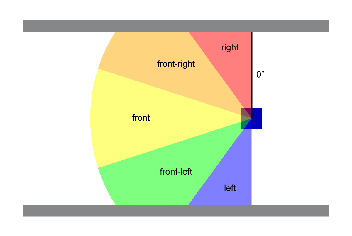
That been done, it is convenient to identify a representative distance for each region. For this reason the minimum distance among all the distances of each region is extracted. The five retrieved values are then used to check the presence of dangerous walls within the visual field of the robot and eventually to avoid them. In particular, according to the distances belonging to the three frontal regions (front, front-left and front-right area), different states are defined, each one related to a different action. Critical states are then further divided in substates, by checking the two side areas:
-
state 1 - "nothing": occurs if no wall is within dangerous distance. The robot is instructed to go forward. -
state 2 - "front": occurs if the minimum distance belonging to the front region is less than the thresholdDAN_DISTANCE. Since given this information it is not really clear where the robot should turn, the side areas are checked as well and three substates are defined:substate a - "right": occurs in the second state if the minimum distance belonging to the right region is less than the thresholdDAN_DISTANCE. The robot is instructed to turn left.substate b - "left": occurs in the second state if the minimum distance belonging to the left region is less than the thresholdDAN_DISTANCE. The robot is instructed to turn right.substate c - "left and right": occurs in the second state if both the minimum distance belonging to the right region and the minimum distance belonging to the left region are less than the thresholdDAN_DISTANCE. The robot is instructed to turn left.
-
state 3 - "front-right": occurs if the minimum distance belonging to the front-right region is less than the thresholdDAN_DISTANCE. The robot is instructed to turn left. -
state 4 - "front-left": occurs if the minimum distance belonging to the front-left region is less than the thresholdDAN_DISTANCE. The robot is instructed to turn right. -
state 5 - "front and front-right": occurs if both the minimum distance belonging to the front region and the minimum distance belonging to the front-right region are less than the thresholdDAN_DISTANCE. The robot is instructed to turn left. -
state 6 - "front and front-left": occurs if both the minimum distance belonging to the front region and the minimum distance belonging to the front-left region are less than the thresholdDAN_DISTANCE. The robot is instructed to turn right. -
state 7 - "front and front-right and front-left": occurs if the minimum distances belonging to all the three frontal regions are less than the thresholdDAN_DISTANCE. Since given this information it is not really clear where the robot should turn, the side areas are checked as well and three substates are defined:substate a - "right": occurs in the seventh state if the minimum distance belonging to the right region is less than the thresholdDAN_DISTANCE. The robot is instructed to turn left.substate b - "left": occurs in the seventh state if the minimum distance belonging to the left region is less than the thresholdDAN_DISTANCE. The robot is instructed to turn right.substate c - "left and right": occurs in the seventh state if both the minimum distance belonging to the right region and the minimum distance belonging to the left region are less than the thresholdDAN_DISTANCE. The robot is instructed to turn left.
The linear and angular velocities that are needed to accomplish all these tasks are published by the controller node on the topic cmd_vel. The stageros node is then responsible for setting them in the simulation.
Finally, since the robot_controller_node already has access to the cmd_vel topic, it is also instructed to act as a server with respect to a service aimed at meeting the requests of the user. In particular, by modifying two coefficients under request (coeff_l and coeff_a), it can:
- start the motion
- increment/decrement the robot velocities
- reset both the robot position and the velocities.
The service used to this end is not made available by the simulation node, so it is created. Its structure consists in a request message made of a char variable (command) and a response message made of a string variable (action).
Before passing on to the GUI node, a representation of the controller node and of the communication channels that connects it with the simulation node is hereafter shown:

Regarding the robot_gui_node, its operating principle is very simple. It asks the user for a command and waits until something is provided. The recognized commands are:
s: start the robot motiond: increment the robot linear velocitya: decrement the robot linear velocityc: increment the robot angular velocityz: decrement the robot angular velocityr: reset the robot position and velocitiesq: quit the GUI node
If the string entered is not among these commands, a warning message is issued on the screen. Otherwise, for the first six elements of this list the node sends a request message containing the correspondent character to the server node and prints the latter's response. These actions are ciclically repeated until the command q, which makes the node terminate, is entered by the user.
The C++ script related to the controller node is composed of a main function, 2 call-back functions and 2 "regular" functions. The first call-back function refers to the server task carried out by the node and is called every time that a request message belonging to the service /change_vel is issued by the client. The second one refers instead to the subscriber task accomplished by the node and is called every time that a message is published on the /base_scan topic.
The main function can be described in pseudocode as follows:
int main (arguments vector dimension, arguments vector){
	initialize the node with the name "robot_controller_node"
	setup the NodeHandle
	initialize the publisher that publishes on the "/cmd_vel" topic
	initialize and define the subscriber that subscribes to the "/base_scan" topic and assign the "robotCallback" call-back function to it
	initialize and define the server that answers to requests belonging to the "/change_vel" service and assign the "obtaincoeffCallback" call-back function to it
	spin to allow the call-back functions to be called whenever a message arrives on the correspondent topic or service
}The first callback function can be described in pseudocode as follows:
bool obtaincoeffCallback (request message related to the service "/change_vel", response message related to the service "/change_vel"){
	if the request message is the command "s"
		if both cefficients are 0
			assign 1 to both the coefficents
			fill the response message with "motion started"
		else
			fill the response message with a warning

	else if the request message is the command "d"
		if the coefficient related to the linear velocity is 0
			fill the response message with a warning
		else
			multiply the coefficient related to the linear velocity by 1.5
			fill the response message with "linear velocity incremented"

	else if the request message is the command "a"
		if the coefficient related to the linear velocity is 0
			fill the response message with a warning
		else
			divide the coefficient related to the linear velocity by 1.5
			fill the response message with "linear velocity decremented"

	else if the request message is the command "c"
		if the coefficient related to the angular velocity is 0
			fill the response message with a warning
		else
			multiply the coefficient related to the angular velocity by 1.2
			fill the response message with "angular velocity incremented"

	else if the request message is the command "z"
		if the coefficient related to the angular velocity is 0
			fill the response message with a warning
		else
			divide the coefficient related to the angular velocity by 1.2
			fill the response message with "angular velocity decremented"

	else if the request message is the command "r"
		assign 0 to both the coefficents
		fill the response message with "position and velocities reset"
}
The second callback function can be described in pseudocode as follows:
void robotCallback(message retrieved by the "/base_scan" topic){
	divide the "ranges" field of the message in 5 subvectors, one for each region
	call the "find_minimum" function to retrieve the minimum distance from the walls for each one of the 5 regions
	print on the screen the obtained minimum distances
	call the "change_direction" function to set the velocities of the robot according to the position of the walls at a dangerous distance and to retrieve the current state and substate
	print on the screen the obtained state and substate
	publish on the "/cmd_vel" topic the velocities set by the "change_direction" function call
}The first "regular" function can be described in pseudocode as follows:
float find_minimum (vector of floats, size of the vector){
	find the minimum value among the elements of the vector passed as input
	return the retrieved minimum element
}
The second "regular" function can be described in pseudocode as follows:
vector of strings change_direction (vector of floats, pointer to the linear velocity of the robot, pointer to the angular velocity of the robot){
	initialize the substate description

	if there is no obstacle at a dangerous distance
		update the state description
		go straight

	else if there is an obstacle at a dangerous distance in the front region
		update the state description
		if there is an obstacle at a dangerous distance in the right region
			update the substate description
			turn left
		else if there is an obstacle at a dangerous distance in the left region
			update the substate description
			turn right
		else
			turn left

	else if there is an obstacle at a dangerous distance in the front-right region
		update the state description
		turn left

	else if there is an obstacle at a dangerous distance in the front-left region
		update the state description
		turn right

	else if there is an obstacle at a dangerous distance in both the front region and the front-right region
		update the state description
		turn left

	else if there is an obstacle at a dangerous distance in both the front region and the front-left region
		update the state description
		turn right

	else if there is an obstacle at a dangerous distance in both the front region, the front-right region and the front-left region
		update the state description
		if there is an obstacle at a dangerous distance in the right region
			update the substate description
			turn left
		else if there is an obstacle at a dangerous distance in the left region
			update the substate description
			turn right
		else
			turn left

	else if there is an obstacle at a dangerous distance in both the front-right region and the front-left region
		update the state description
		go straight

	else
		update the state description

	return a vector containing both the state description and the substate description
}As regards the GUI node instead, its structure is much simpler since it consists in only the main function.
The main function can be described in pseudocode as follows:
int main (arguments vector dimension, arguments vector){
	initialize the node with the name "robot_gui_node"
	setup the NodeHandle
	initialize and define a client ("client1") that sends requests belonging to the "/change_vel" service
	define the custom service variable "srv1" of type "ChangeVel"
	initialize and define a client ("client2") that sends requests belonging to the "/reset_positions" service
	define the service variable "srv2" of type "Empty"
	initialize an iterations counter related to the linear velocity of the robot to 0
	initialize an iterations counter related to the angular velocity of the robot to 0

	print the instructions to interact with the node on the screen

	while true
		ask the user for a command
		retrieve the command entered by the user on the stdin

		if the entered command is "s"
			check if the server related to the "/change_vel" service is up and running
			fill the request message of the variable "srv1" with the character "s"
			make the first client call the related service with the variable "srv1"

			print the server response on the screen

		else if the entered command is "d"
			check if the server related to the "/change_vel" service is up and running
			fill the request message of the variable "srv1" with the character "d"
			make the first client call the related service with the variable "srv1"

			if the response is a warning
				print the server response on the screen in red
				assign 0 to the iterations counter related to the linear velocity of the robot
			else
				print the server response on the screen in green
				increment the iterations counter related to the linear velocity of the robot

		else if the entered command is "a"
			check if the server related to the "/change_vel" service is up and running
			fill the request message of the variable "srv1" with the character "a"
			make the first client call the related service with the variable "srv1"

			if the response is a warning
				print the server response on the screen in red
				assign 0 to the iterations counter related to the linear velocity of the robot
			else
				print the server response on the screen in green
				decrement the iterations counter related to the linear velocity of the robot

		else if the entered command is "c"
			check if the server related to the "/change_vel" service is up and running
			fill the request message of the variable "srv1" with the character "c"
			make the first client call the related service with the variable "srv1"

			if the response is a warning
				print the server response on the screen in red
				assign 0 to the iterations counter related to the angular velocity of the robot
			else
				print the server response on the screen in green
				increment the iterations counter related to the angular velocity of the robot

		else if the entered command is "z"
			check if the server related to the "/change_vel" service is up and running
			fill the request message of the variable "srv1" with the character "z"
			make the first client call the related service with the variable "srv1"

			if the response is a warning
				print the server response on the screen in red
				assign 0 to the iterations counter related to the angular velocity of the robot
			else
				print the server response on the screen in green
				decrement the iterations counter related to the angular velocity of the robot

		else if the entered command is "r"
			check if the server related to the "/change_vel" service is up and running
			fill the request message of the variable "srv1" with the character "r"
			make the first client call the related service with the variable "srv1"

			print the server response on the screen
			assign 0 to both the iterations counters

			check if the server related to the "/reset_position" service is up and running
			make the second client call the related service with the variable "srv2"

		else if the entered command is "q"
			exit
		else
			print "invalid command" on the screen

		if the iterations counter related to the linear velocity of the robot is greater than 3
			issue a warning message on the screen
		if the iterations counter related to the angular velocity of the robot is greater than 3
			issue a warning message on the screen

	return
}As far as the limitations of the script are concerned, the main one is that, by increasing the velocities too much, the control of the robot might fail. In the proposed solution the GUI node issues a warning message on the screen if at least one of the velocities is too high. Another way to deal with this problem could be to simply not allow the user to increment the velocities once that they reached a certain value.
As regards the improvements instead, several of them could be carried out. For instance, one of them could be to allow the user to directly specify the desired velocities by means of the GUI node.