In this project, a ESP32 microcontroller is used along with a Blynk app to actuate a strip of 62 WS2812B LEDs over WiFi.
Note that there's also a MP34DT01-M PDM MEMS Microphone that is being used to make the LEDs respond to the current sound volume level.
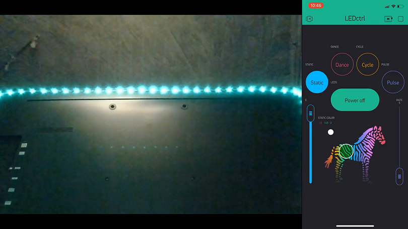
Click here to view the LEDctrl demostration video.
- ESP32 + WiFi Onboard
- WS1228B Addressable RGB LEDs strip
- 5V 10A DC Power Supply
- MP34DT01-M PDM MEMS Mic Breakout
NOTE: Please take a look at the Schematic/LEDctrl_Schem.png to see the LEDctrl project schematic which shows the appropriate wiring of each component mentioned just above.
After downloading the Arduino IDE software, you'd need to install the following Arduino IDE libraries/packages to be able to compile, upload, and run the LEDctrl.ino source code
Next, you'll need to create an LEDctrl Blynk App using the provided clone barcode. Once you've created a Blynk Mobile App, you'll receive an authentication token via email.
After that, open the LEDctrl.ino code, using Arduino IDE, and edit the following:
- Copy and paste the authentication token you've received upon creating an LEDctrl Blynk Mobile App into
char auth[].
// You should get Auth Token in the Blynk App.
// Go to the Project Settings (nut icon).
char auth[] = "Your Auth Token";- Add your WiFi SSID name and Password into
char ssid[]&char pass[], respectively:
// Your WiFi credentials.
// Set password to "" for open networks.
char ssid[] = "SSID";
char pass[] = "PASSWORD";- Change the number of LEDs/Pixel in the used LEDs' strip and the designated signal pin for the LEDs:
/*<------------------------ NeoPixel LED Ring Macros and Global Variables ------------------------>*/
#define LED_PIN    A1		//Designated pin to set addressable LEDs signal (LEDs' Data In)
#define LED_COUNT  62		//Number of LEDs/Pixel in a strip
Note that you don't have to change the designated pin (A1) if you've implemented the wiring in the Schematic/LEDctrl_Schem.png diagram.
- Change the designated DATA pin & Clock pin of the PDM MEM Microphone:
#define I2S_WS_PIN     21          //I2S Word Select pin on ESP32 (GPIO 21)
#define I2S_DATA_PIN   17          //I2S Data pin on ESP32 (GPIO 17)
Note that you don't have to change the designated pins (21 & 17) if you've implemented the wiring in the Schematic/LEDctrl_Schem.png diagram.
Now, compile and upload the LEDctrl.ino source code you've just edited onto your ESP32 Microcontroller by clicking the Arduino IDE Compile & Upload button/arrow.
There has been some instances where the Mic's configuration (in software) might produce faulty measurements (i.e., reading a high volume spike/pulse even though there are no loud sound/noise in the background). This could happen if you are using another I2S Microphone (beside MP34DT01-M PDM MEMS Mic Breakout) and/or another Microcontroller (beside Huzzah32).
With that being said, I recommend that you test out the Mic's input, using the provided code, to see if you are reading any faulty measurements. After that, you can change the following flags and variables in the I2S configuration to obtain a better and more accurate reading:
- In some cases, changing the DMA buffer size (
DMA_BUFF_LEN) to1024, the Sample Rate (SAMPLE_RATE) to8000, and the DMA buffers count (DMA_BUFF_CT) to4may produce more accurate results, however, I recommend that you try other values as well.
const int DMA_BUFF_CT = 2;         //number of DMA buffer (minimum 2)
const int DMA_BUFF_LEN = 32;       //samples per DMA buffer (minimum 8)
const int SAMPLE_RATE = 44100; //44.1kHz- You might also want to change the number of bits per sample (
.bits_per_sample) and the I2S channel format (.channel_format). In some case, changing the bits per sample toI2S_BITS_PER_SAMPLE_32BITand the channel format toI2S_CHANNEL_FMT_ONLY_LEFT(orI2S_CHANNEL_FMT_ONLY_RIGHT) may produce better results. You can found these under theMicInit()function as shown below:
/*Initializes I2S bus to start reading Mic input*/
void MicInit(){
  esp_err_t err;

// The I2S config
  i2s_config = {
    .mode = i2s_mode_t(I2S_MODE_MASTER | I2S_MODE_RX | I2S_MODE_PDM),     // Receive, not transfer
    .sample_rate = SAMPLE_RATE,
    .bits_per_sample = I2S_BITS_PER_SAMPLE_16BIT,                         //Number of bits per sample
    .channel_format = I2S_CHANNEL_FMT_RIGHT_LEFT,                         //Do not connect SEL pin.
    .communication_format = i2s_comm_format_t(I2S_COMM_FORMAT_I2S | I2S_COMM_FORMAT_I2S_MSB),
    .intr_alloc_flags = ESP_INTR_FLAG_LEVEL1,                             // Interrupt level 1
    .dma_buf_count = DMA_BUFF_CT,                                         // number of buffers
    .dma_buf_len = DMA_BUFF_LEN                                           // samples per buffer
  };
...
...
}NOTE: if you did change the .bits_per_sample, then I would suggest that you change the number of bits read by i2s_read() function. The i2s_read() function-call can be found under MicNormValue() function, as shown below.
float MicNormValue(){
  // Read multiple samples at once
  int err = i2s_read(I2S_PORT, &samples, sizeof(uint16_t)*DMA_BUFF_LEN, &num_bytes_read,  (500 / portTICK_RATE_MS));  //reads two bytes (16-bit)
...
...
}
You can change the number of bits read by i2s_read() function by changing the third argument sizeof(uint16_t) to whicever desired size you picked. I.e., if you've picked I2S_BITS_PER_SAMPLE_32BIT then you'd change the sizeof(uint16_t) to sizeof(uint32_t).