95 Eurorack tutorial
This short tutorial explains how to interface a 3.3V Raspberry Pi (or MCU) with Eurorack using an external I2C DAC.
The example uses a Raspberry Pi, but the same wiring and concepts apply to most microcontrollers.
⚠️ Important
Eurorack typically uses higher voltages (0–10V, ±5V, or ±10V), while RPis and MCUs use 3.3V logic.
Never connect GPIO pins directly to Eurorack signals.
- Raspberry Pi GPIOs are 3.3V logic only
- Eurorack CV usually expects higher voltage ranges
- An external DAC provides accurate analog output
- Powering the DAC at 5V allows up to 5V output, which can then be scaled for Eurorack
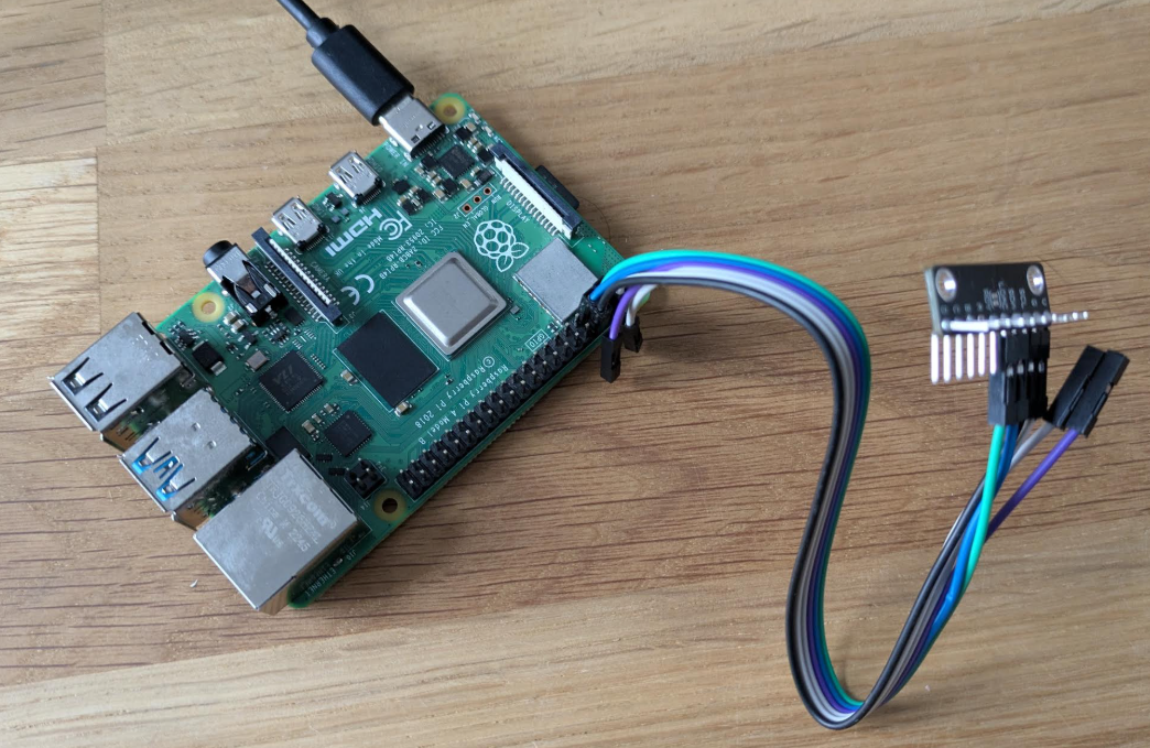
- Raspberry Pi
- I2C DAC module MCP4728
Even though the Raspberry Pi uses 3.3V for its GPIO and I2C communication, the MCP4728 is "5V tolerant" and can be powered by the Pi's 5V rail to achieve a full 0–5V output range.
| DAC Pin | Raspberry Pi Pin | Notes |
|---|---|---|
| VCC | 5V | Power DAC for 0–5V output |
| GND | GND | Common ground (required) |
| SDA | SDA (GPIO 2) | I2C data SDA (3.3V logic) |
| SCL | SCL (GPIO 3) | I2C clock SCL (3.3V logic) |
Key point:
- VCC must be connected to 5V, not 3.3V
- This allows the DAC to output up to 5V
Enable I2C using:
sudo raspi-configThen:
- Interface Options → I2C → Enable
- Reboot the Raspberry Pi
To verify that the DAC is correctly connected to the I2C bus, run:
i2cdetect -y 1If everything is wired correctly, you should see a device address (for example 0x60):
     0 1 2 3 4 5 6 7 8 9 a b c d e f
60: 60 -- -- -- -- -- -- -- -- -- -- -- -- -- -- --
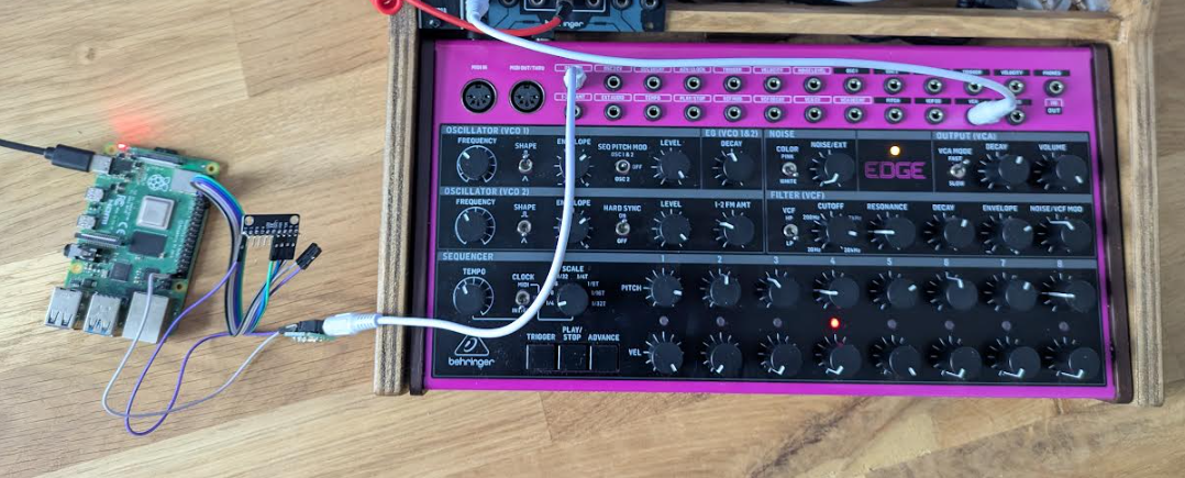
For testing purposes, we will connect the DAC directly to a Eurorack input.
This is acceptable for short tests, but not recommended for long-term or final designs.
Later on, you must add proper protection, including:
- Output buffering (op-amp)
- Current limiting resistors
- ...
- Connect a mono jack to the DAC output
- Tip (head) of the jack → DAC output pin (D / VOUT)
- Sleeve (ground) of the jack → DAC GND
The following C++ program writes a continuously changing sine wave value to the DAC, creating a simple LFO-style control voltage.
It:
- Uses I2C on
/dev/i2c-1 - Assumes a DAC address of
0x60 - Outputs a sine wave mapped to the full DAC range
Compile and run this code on the Raspberry Pi.
#include <iostream>
#include <fcntl.h>
#include <unistd.h>
#include <sys/ioctl.h>
#include <linux/i2c-dev.h>
#include <cmath>
#include <chrono>
#include <thread>

int main() {
    const char *bus = "/dev/i2c-1";
    int addr = 0x60;
    int file;

    if ((file = open(bus, O_RDWR)) < 0) return 1;
    if (ioctl(file, I2C_SLAVE, addr) < 0) return 1;

    double angle = 0.0;
    const double increment = 0.1; // Controls the LFO speed

    std::cout << "Starting LFO on DAC output. Press Ctrl+C to stop." << std::endl;

    while (true) {
        // Generate sine value between -1.0 and 1.0
        double sine_val = sin(angle);

        // Map -1.0...1.0 to 0...4095 (12-bit DAC)
        unsigned short val =
            static_cast<unsigned short>((sine_val + 1.0) * 2047.5);

        unsigned char buffer[3];
        buffer[0] = 0x46;               // Channel D command
        buffer[1] = (val >> 8) & 0x0F;  // High bits
        buffer[2] = val & 0xFF;         // Low bits

        if (write(file, buffer, 3) != 3) {
            std::cerr << "I2C Write Error" << std::endl;
            break;
        }

        angle += increment;
        if (angle > 2 * M_PI) angle -= 2 * M_PI;

        // Update rate: 10 ms (≈100 Hz)
        std::this_thread::sleep_for(std::chrono::milliseconds(10));
    }

    close(file);
    return 0;
}
Compile and run:
g++ dac_test.cpp -o dac_test
sudo ./dac_testThis program generates a slow sinusoidal control voltage, effectively acting as a simple LFO.
You should observe:
- Smooth modulation on a Eurorack CV input
- Voltage swinging between approximately 0V and 5V
Again, this direct connection is only for testing.
For real Eurorack modules, always add proper output conditioning and protection.