Real-Time Location System based on RFID, developed as the Control and Automation Engineering final project, in November 2018.
Contains the academic materials developed in the project:
Contains all the code developed in the project, basically divided into 2 parts:
.NET application code for capturing, processing, and displaying data (Language: C#)
Python code to generate the neural networks of the system and the generated models.
The location software developed in this work was named Prox!Locator and had the objective of calculating the position of a mobile tag by receiving UDP packets from checkpoints. To do this, it was his responsibility to receive the packets, organize the received data and perform the position calculation.
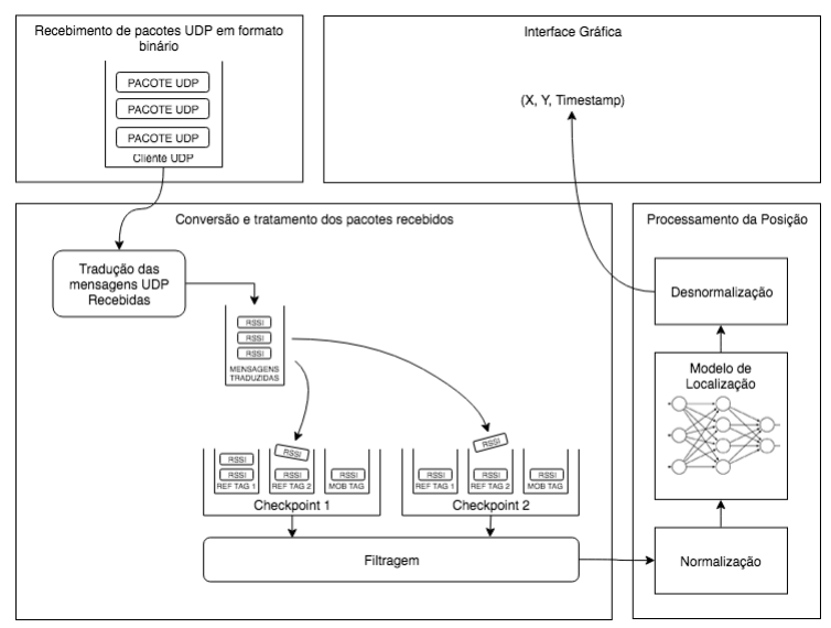
To ensure system scalability and enable changes such as adding antennas and tags, changing calculation models, and including additional business rules, Prox!Locator was organized into components, as shown in Figure 4.1, and with the following responsibilities:
- Receiving UDP packets, managing connections, and sending received packets to the components responsible for their interpretation;
- Translation of received messages, organization of RSSI values by tag/antenna, filtering and sending data in the correct format for position calculation;
- Calculation of the tag position through the obtained RSSI values;
- Presentation of received and/or processed data to the user, through a graphical interface.
The main technology chosen for the development of the system was the .NET Framework and the C# language, due to their robustness, wide variety of available libraries, and consolidation in the market. The framework features native libraries for using UDP sockets, data structures, and thread management, among other features needed during development.
The graphical interface uses Windows Presentation Foundation (WPF), a framework for developing graphical interfaces contained in the .NET Framework. The platform is widely used for developing applications for Windows and shares the advantages of the .NET Framework.
Due to the research done in the blueprint phase, artificial neural networks were chosen as the basis of the project's location model. While there are libraries for designing, testing and running neural networks in the .NET Framework, other technologies have better capabilities and are more recommended for this type of analysis. Thus, the initial modeling of the neural networks used in the project is done using the MATLAB Neural Network libraries and the implementation and training of these networks is done using the Python language. Finally, neural network models developed in Python can be exported and implemented within the .NET Framework, through the use of the NNSharp library.
System components were specified through interfaces. Interfaces are contracts that define the methods and properties of the classes without defining their implementation. This approach provides some advantages, as it allows components that implement the same interface to be replaced with each other without having to be refactored.
Concrete classes are implementations of the interfaces, containing all the logic necessary to provide the methods and properties expected by them. The figure below shows the interfaces and concrete implementations of the components foreseen in the architecture. In this way, each component created during the project can not only be used separately but also can be reused within the application itself.
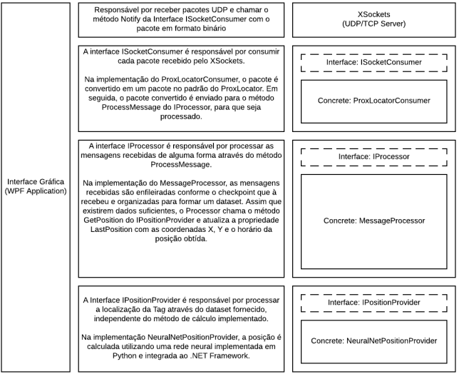
The first component of the system is the packet receiver, responsible for creating a UDP client, receiving messages, and sending the received packets to a packet consumer. This component takes as inputs the port and where the UDP client should run and the data consumer. This layer was developed within a library called XSockets, which follows the following pseudocode:
- It receives a consumer object (which implements the ISocketConsumer interface) and the port number that will be used by Socket in its constructor
- Starts a UDP client on the specified port
- Wait for new messages
- Calls the Consumer component's Notify() method whenever a new message is received
The second component is the consumer which must be injected into the packet receiver. This component implements the ISocketConsumer interface and is responsible for handling packets received by the UDP client.
The ISocketConsumer interface requires consumers to implement the following methods:
- SetSocket(Socket socket): Method used to create a communication channel between the application and the endpoint that sent the message
- Notify(byte[] message, IPEndPoint endpoint): Method called every time a new binary message is received by the clientUDP of this method, all processing logic of the received data must be implemented.
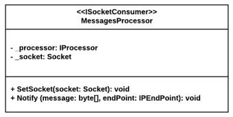
The concrete implementation of the consumer was done in the *ProxLocatorConsumer class, represented by the class diagram below. In its Notify method, the consumer decodes the received binary packet and creates an instance of a message object, containing the tag identifier, the checkpoint IP that received the message and the received RSSI value. It then sends this decoded packet to the next component, the processor, via the ProcessMessage method.
The third component is the processor that must be injected into the Package Consumer. This component implements the IProcessor interface and is responsible for all the logical processing of messages to obtain the position, such as separating messages in queues by checkpoint and tag, filtering, discarding inappropriate messages, organization of * datasets*, calling the calculation engine and making the last position obtained available.
The IProcessor interface requires processors to implement the following methods and properties:
- LastPosition: Property that indicates the last calculated position, with the calculation date/time and x and y positions;
- ProcessMessage(LocatorMessage message): Method called every time a new message is translated in the consumer. This method is the logical input for all the processing done in this step.
The MessagesProcessor is called every time a new message is received and must be able to process these messages regardless of the order in which they arrive. For this, it has an internal data structure to store the received messages in queues.
This structure, presented in the class diagram of the figure below, consists of a list of objects of type Checkpoint. Each checkpoint encapsulates a list of Tags and has methods for queuing and dequeuing messages. Each tag has a queue to store incoming messages and a filter. Thus, each received message is filtered and stored in a queue referring to its *tag/checkpoint pair.
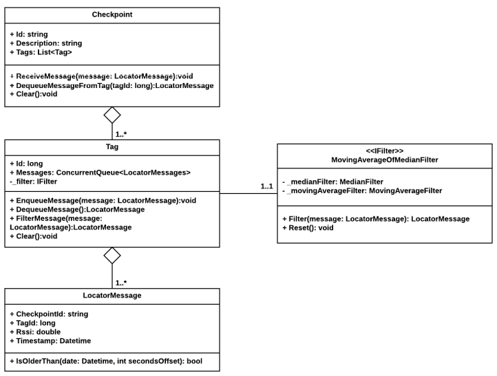
The filter is implemented from the IFilter interface and must have a method for filtering and another for cleaning the internal buffer. For the Prox!Locator project, a moving average filter, a median filter, and a median moving average filter, composed of the previous two, were implemented.
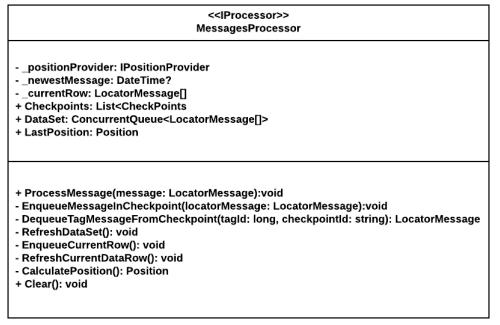
In the figure below it is possible to see the main class of MessageProcessor, with the methods and properties defined in it. As messages arrive and are queued, the processor checks that there is enough data to predict the private methods RefreshDataSet, EnqueueCurrentRow, and RefreshCurrentDataRow.
If there are RSSI values from the same moment for all tags and checkpoints, these data are sent to the position estimator through the CalculatePosition method, which returns the calculated position. This position is available in the LastPosition public property, accessible by external components (such as the UI).
The position estimator is the component responsible for calculating the position of the tag through a vector of received messages. The technique used and the data needed in this vector depend on the chosen implementation.
The IPositionProvider interface defines the following method:
- GetPosition(LocationMessage[] dataRow): Method that receives a vector of position messages and returns the calculated position.
The MessagesProcessor is called every time a new message is received and must be able to process these messages regardless of the order in which they arrive. For this, it has an internal data structure to store the received messages in queues.
This structure, presented in the class diagram of the figure below, consists of a list of objects of type Checkpoint. Each checkpoint encapsulates a list of Tags and has methods for queuing and dequeuing messages. Each tag has a queue to store incoming messages and a filter. Thus, each received message is filtered and stored in a queue referring to its *tag/checkpoint pair.
The filter is implemented from the IFilter interface and must have a method for filtering and another for cleaning the internal buffer. For the Prox!Locator project, a moving average filter, a median filter, and a median moving average filter, composed of the previous two, were implemented.
In the figure below it is possible to see the main class of MessageProcessor, with the methods and properties defined in it. As messages arrive and are queued, the processor checks that there is enough data to predict the private methods RefreshDataSet, EnqueueCurrentRow, and RefreshCurrentDataRow.
If there are RSSI values from the same moment for all tags and checkpoints, these data are sent to the position estimator through the CalculatePosition method, which returns the calculated position. This position is available in the LastPosition public property, accessible by external components (such as the UI).
The position estimator is the component responsible for calculating the position of the tag through a vector of received messages. The technique used and the data needed in this vector depend on the chosen implementation.
The IPositionProvider interface defines the following method:
- GetPosition(LocationMessage[] dataRow): Method that receives a vector of position messages and returns the calculated position.
During the Characterization of the Models chapter, different positioning models were evaluated. At the end of the experiments, it was found that topology model 4 had the best performance for the proposed problem. Thus, this model was implemented within the Position Estimator of ProxLocator, through neural networks.
First, the models were assembled and trained using the Python language and the Keras library. They were then exported to a json file and later imported into C# code, using the NNSharp library.
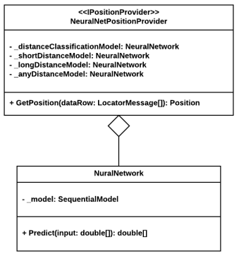
Within the NeuralNetPositionProvider class, represented by the class diagram in the figure below, the imported neural networks were encapsulated in objects of type NeuralNetwork. Upon receiving the RSSI data through the GetPosition method, the estimator calculates the position according to the algorithm defined for the model:
- Calculates the probability of the distance is greater than 3.5 meters through the classification neural network (distanceClassificationModel);
- If the probability is less than 0.35, the neural network trained for distances less than 3.5 meters is used (shortDistanceModel);
- If the probability has a value between 0.35 and 0.65, a trained neural network is used for all distances (anyDistanceModel);
- If the probability has a value greater than 0.65, a neural network trained for distances greater than 3.5 meters is used(longDistanceModel).
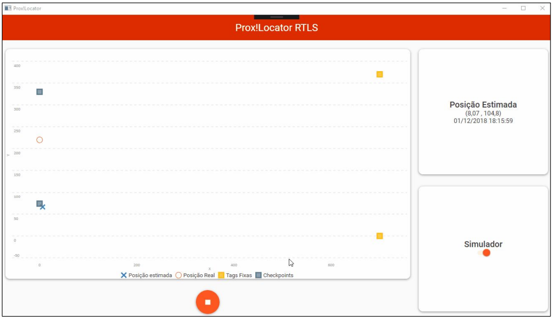
The Prox!Locator's user interface was made using Windows Presentation Foundation (WPF) in order to not only present the real-time position of tags, but also to control the execution of the mechanism for receiving packets / position processing.
The structure of the graphical application was based on the MVVM (Model View ViewModel) architecture pattern, which aims to separate the application logic from the implemented graphical interface. Thus, two classes were created:
- MainWindow.cs/MainWindow.xaml: Class where all graphical elements of the screen are defined and organized through a file in the XAML standard.
- ProxLocatorViewModel: Class where all data processing is done and the values that will be displayed on the screen are made available.
When creating the screen in the MainWindow class, the WPF framework allows a property called DataContext to be set. Thus, this property is defined as ProxLocatorViewModel, and the application makes the logical connection between the class properties and the graphical interface.
In the graphical interface, shown in the figure below, the following elements are displayed:
- A graph showing the position of the checkpoints, fixed tags, real location of the mobile tag (in the case of simulation) and its estimated location;
- A card with the estimated coordinates of the tag and the date/time of the last calculation made;
- A position calculation start and stop button;
- One switch for simulation mode selection
If simulation mode is off, the program will start the UDP packet receiver and all message processing and position calculation components. If the simulation mode is activated, the processing components will be started without the receiver of UDP packets and the RSSI data will be obtained from a text file.
The application start/stop buttons are used to start and stop message processing, which has the results displayed in real time both on the position graph and on the results card.