Semi sphere
In this tutorial we will cover generating a high order mesh containing a boundary layer about half of a sphere with a symmetry plane. This case is located in the Demo/SymmetricSphere directory and will reference the geometry file Sphere25CSymmetry.stp. The GMSH configuration file SphereSymmetry.geo is shown below.
ff_len = 10;
max_lan = ff_len;
surf_len = 0.1;
dist = 10.0;
cuttof_dist = 1;

Geometry.Tolerance = 1.0e-12;

Mesh.CharacteristicLengthFactor=2.0;

Mesh.CharacteristicLengthMax = ff_len;

Mesh.SaveParametric = 1;

Merge "Sphere25CSymmetry.stp";


Physical Line(0) = {1:24};

Physical Surface(20) = {10};
Physical Surface(6) = {5:9};
Physical Surface(7) = {1:4};

Physical Volume(0) = {1};

Field[5] = Box;
Field[5].VOut = ff_len;
Field[5].VIn = surf_len;
Field[5].XMax = 1;
Field[5].XMin = -1;
Field[5].YMax = 1;
Field[5].YMin = -1;
Field[5].ZMax = 1;
Field[5].ZMin = -1;

Field[6] = Box;
Field[6].VOut = ff_len;
Field[6].VIn = 0.25;
Field[6].XMax = 10;
Field[6].XMin = -1.5;
Field[6].YMax = 2;
Field[6].YMin = -2;
Field[6].ZMax = 2;
Field[6].ZMin = -2;


Field[8] = Box;
Field[8].VOut = ff_len;
Field[8].VIn = surf_len;
Field[8].XMax = 0.75;
Field[8].XMin = -0.75;
Field[8].YMax = 0.75;
Field[8].YMin = -0.75;
Field[8].ZMax = 0.75;
Field[8].ZMin = -0.75;

Field[10] = Min;
Field[10].FieldsList = {5,6,8};

Background Field = 10;
The configuration is similar to that of the RAE2822 airfoil, the primary difference being that we specify the boundary conditions as Physical Surfaces rather than Physical Lines. In this case, we set the far-field to have a physical ID of 6, the symmetry plane to have an ID of 20, and the semi-sphere surface to have an ID of 7. Note that for 3D cases we must now specify Physical Volume(0) = {1} in contrast to the 2D case where we specified a physical surface. Also, we need count the number of lines in the step model (24, in this case) and add the following line:
Physical Line(0) = {1:24};
This is required in 3D in order to force GMSH to write out the appropriate elements along with their physical entities.
To generate the mesh, we can use the following GMSH command:
gmsh -3 -optimize -smooth 3 SphereSymmetry.geo
which creates a mesh named SphereSymmetry.msh. The -optimize argument tells GMSH to optimize the 3D mesh, while the -smooth 3 argument tells GMSH to apply three smoothing iterations. It is recommended that users optimize and smooth 3D meshes, unless an anisotropic meshing algorithm is used (more on this in the next tutorial).
We will now generate a p=4 mesh with optimized nodal interpolation points using MeshOpt. The MeshOpt.config file for this case is replicated below.
CaseParameters{
	GMSHFileName = SphereSymmetry.msh;
	STEPFileName = /home/john/Dropbox/Rhino3D/SolidSphere/Sphere25CSymmetry.stp;
}

BLParameters{
	GenerateBL = true;
	Thickness = 0.4;
	NLayers = 4;
	BLSurfID = 7;
	BLTermID = 20;
}

HighOrderParameters{
	Order = 4;
	TargetMinQuality = 0.9;
        OptimizedNodeSpacing = true;

}
This configuration file is essentially identical to that of the RAE2822 case, the primary difference being the number of layers and target thickness, and specification of the symmetry plane physical ID with BLTermID = 20. Note that we must specify a BLTermID since we would like the boundary layer to terminate at the symmetry plane. We can now execute MeshOpt in the working directory, and a file named meshopt.msh will be generated, since no value for OutputFileName was specified.
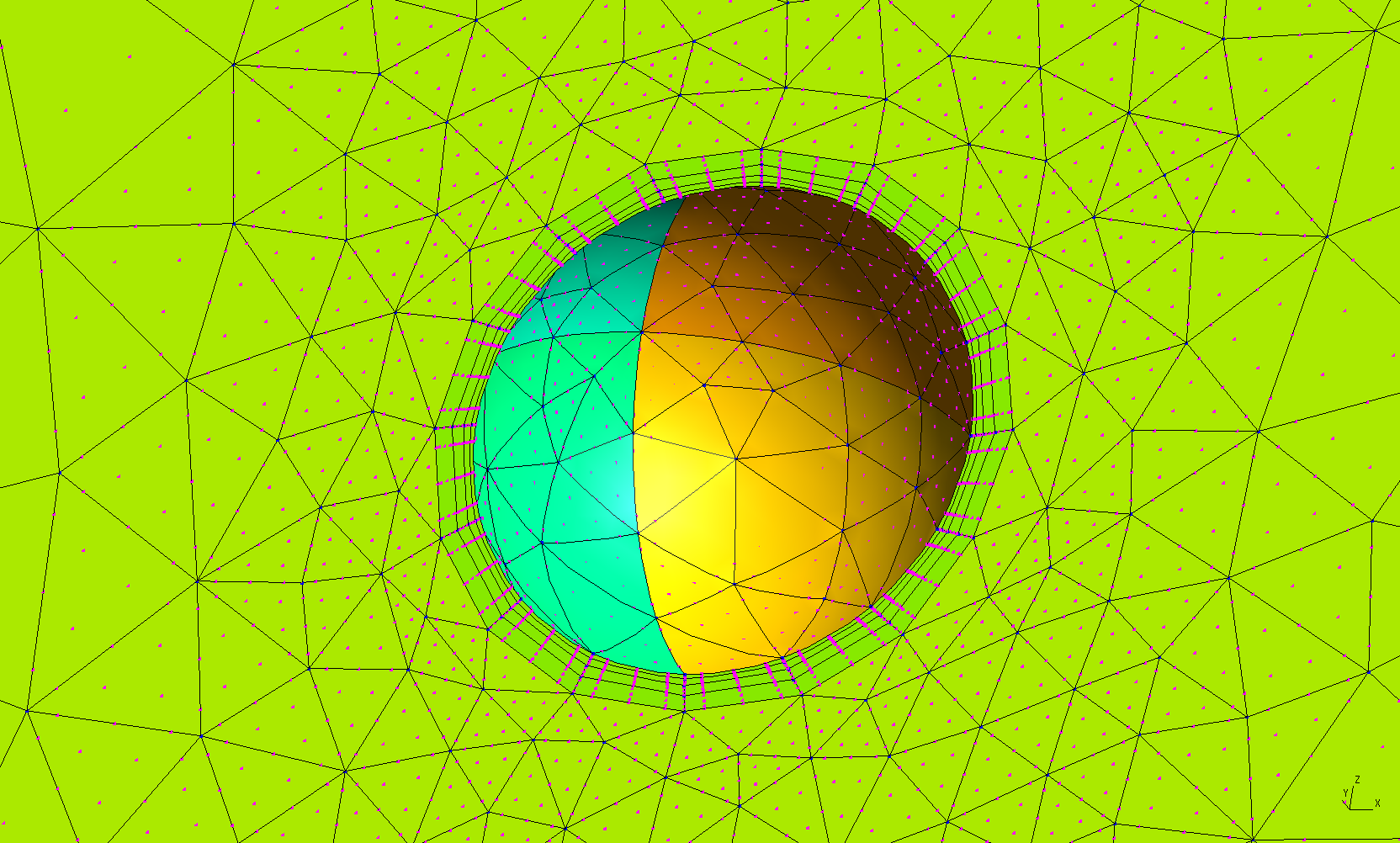
Upon inspecting the mesh, we can see something odd going on near the element vertices. The problem is that GMSH is reading in elements that use optimized nodal interpolation points but performing the high order visualization using equispaced points. Note that if we generate the mesh with equispaced nodes, the mesh will look fine.
Also note that the boundary layer thickness is not anywhere close to the prescribed 0.4 -- it appears to only be 0.1 or so. This is one of those cases where we had to request a larger boundary layer thickness than desired in order to obtain a valid high order boundary layer mesh. We are working on making boundary layer generation more robust.