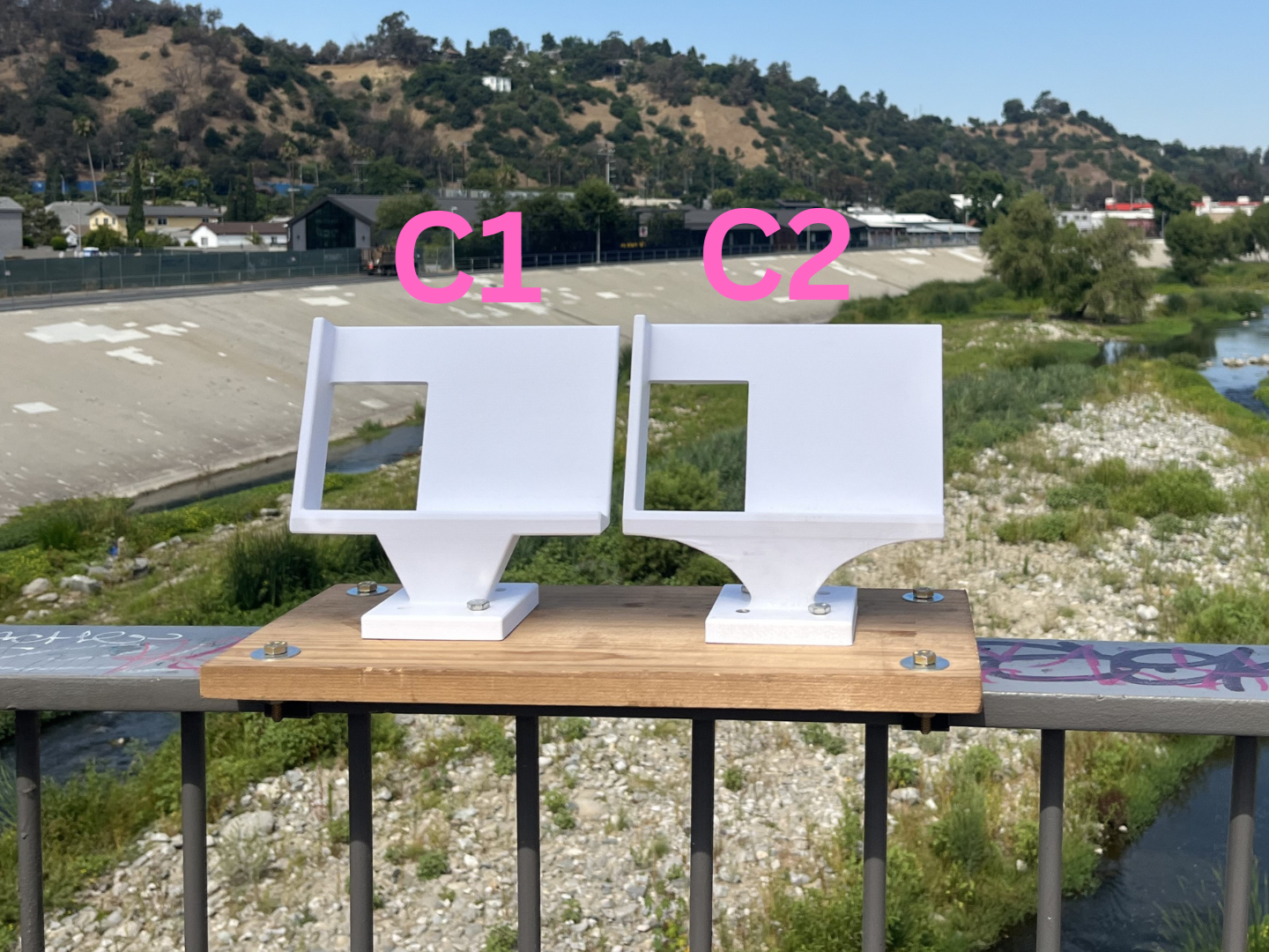
Camera systems with multiple angles ("stereo camera systems") allow for the 3D reconstruction of a photographed scene. We built one such stereo camera structure to monitor the Los Angeles River through community photographs. Community members place their phones in the system, take photographs, and then submit them, supporting our research. The process for building this system is detailed in this Instructable: https://www.instructables.com/Phone-Stand-for-Digitizing-the-Outdoors-in-3D/.
However, there may be discrepancies between a community member's photographs and the photographs taken by the phones used for calibration: Community members may be using other phone models, submissions may be incorrectly formatted (portrait vs. landscape)[1], etc.
This code supports the automatic and manual alignment of photographs, aligning the submitted photos to a set of calibrated reference photos so that the submitted photos can be used for 3D reconstruction. The scene is then reconstructed based on the existing calibration for our stereo camera system to create a 3D point cloud.
- Download and unzip the repository.
- Make sure you have MATLAB 2023a with the Computer Vision, Machine Learning, and LIDAR toolboxes installed.
- Open
stereoCam_main.m.
Note that the system was designed for use with MATLAB version 2023a. Other versions of MATLAB may require alterations in the code for correct syntax.
There are many options for alignment for aligning citizen scientist-submitted photographs (referred to as ‘input photos’) to the photographs used for calibration (referred to as ‘reference photos’). Depending on the situation, different options may be better suited.
In manual alignment, the user describes several distinct features (‘ground control points’) visible in both images in a text file, then manually selects each feature in each image. Based on the location of these selected features, the input photo is transformed to match the reference photo.
If the input and reference photos are from very different time points or otherwise visually very different, manual alignment may be best.
-
Describe each ground control point on a separate line in a text document.
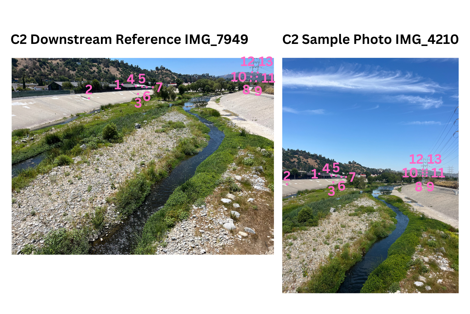
Sample GCP Point Names.txtandSample GCP Point Names 2.txtare provided as examples for the C1 and C2 sample images, respectively. The ground control points described in these files are labeled below.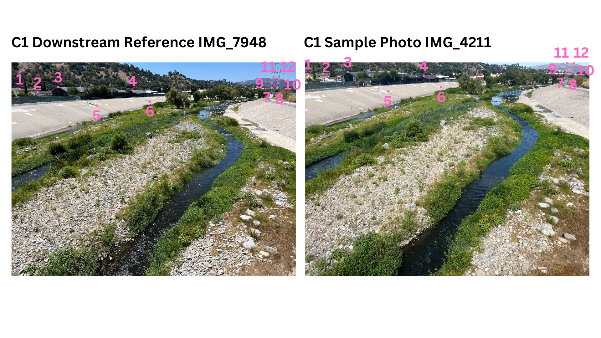
-
Replace
C1_input_filepath,C2_input_filepath,C1_reference_filepath, andC2_reference_filepathwith the desired files or use the sample file paths already provided. -
Apply
stereoCam_alignImageswith your filepaths, the desired output image filetype, the text file, and ‘Manual’ for’DetectionMethod’. An example is provided in Option 1 ofstereoCam_main.m. -
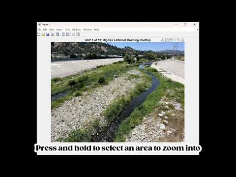
Select the ground control points as accurately as possible in the input and reference photos. A video guide for GCP selection is below.
-
The aligned image will be saved as
[photo file name]_registered.[registration file type]. -
Apply
stereoCam_reconstructSceneto the two registered input photos to create your 3D reconstruction.
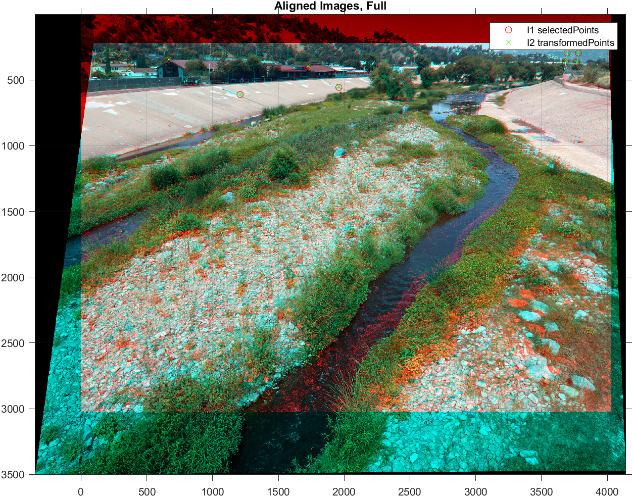
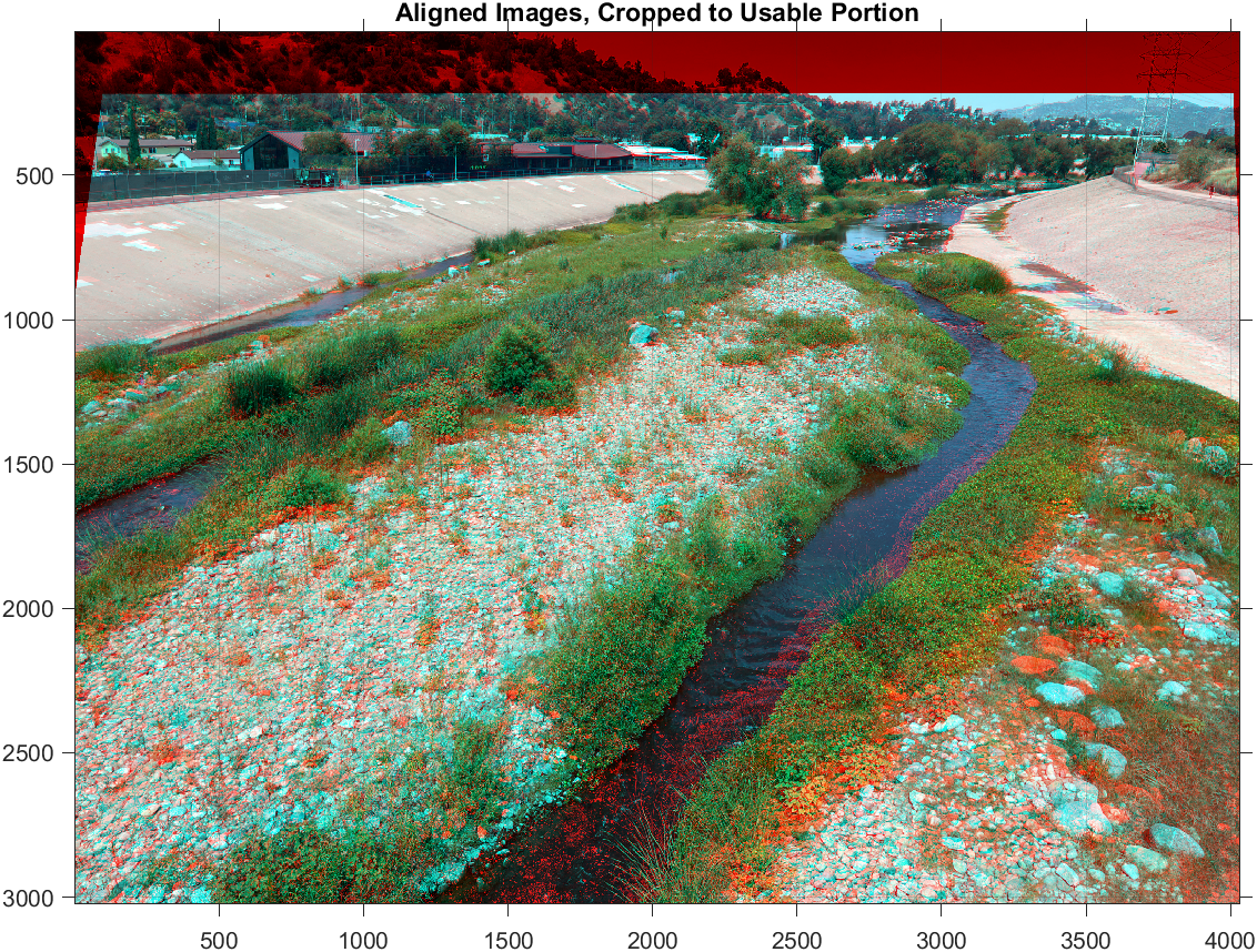
The figures below were generated using the ground control points in Sample GCP Point Names.txt to align C1 Sample Photo IMG_4211 (input) to C1 Downstream Reference IMG_7948.jpg (reference). In the anaglyphs, the reference image is shown in red, and the input image is shown in cyan. There are several regions where the true color is visible, indicating the alignment worked well in these regions.
The photos’ ground control points will be saved as [photo file name]_GCP.mat. If these same photos are reused, these .mat files can be loaded in as the reference_photo_GCP and unaligned_photo_GCP inputs to stereoCam_alignImages. If both have been previously selected, no text file is necessary. An example is provided in Option 2 of stereoCam_main.m.
In automatic alignment, a feature detection-description method is used to find and characterize local features in the images. Corresponding features are then matched using a Random Sample Consensus (RANSAC) method to determine how the input image can be transformed to match the reference image.
Three automatic feature detection-description methods are offered by stereoCam_alignImages:
- SIFT, Scale-Invariant Feature Transform[2] (default)
- SURF, Speeded Up Robust Features[3]
- BRISK, Binary Robust Invariant Scalable Keypoints[4]
These three feature detection-description methods were chosen for being the most scale-invariant methods, valuable given the various zoom settings that users may have on their phones.[5] Previous literature reports that SIFT and BRISK are two of the most accurate methods for image registration.[5] However, I found it was worthwhile to test all three on the first few sets of images to determine which worked best.
- Replace
C1_input_filepath,C2_input_filepath,C1_reference_filepath, andC2_reference_filepathwith the desired files or use the sample file paths already provided. - Apply
stereoCam_alignImageswith your filepaths, the desired output image filetype, the text file, and ‘SIFT’, ‘SURF’, or ‘BRISK’ for’DetectionMethod’. An example is provided in Option 3 ofstereoCam_main.m. - The aligned image will be saved as
[photo file name]_registered.[registration file type]. - Apply
stereoCam_reconstructSceneto the two registered input photos to create your 3D reconstruction.
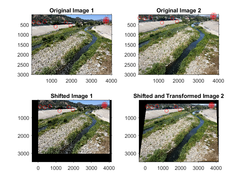
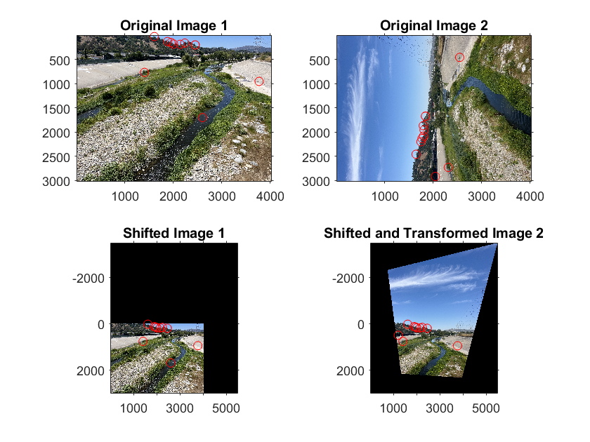
The figures below were generated using the SIFT method to align C2 Sample Photo IMG_4210 (input) to C2 Downstream Reference IMG_7949.jpg (reference). Note that the system is able to handle rotated images.
If there are regions in the images that share no features in common and may therefore confuse the image alignment, you may consider using a mask. All features identified by the automatic algorithm within the polygon mask will be ignored during feature matching, preventing their influence on the final alignment.
-
When calling
stereoCam_alignImages, setuseMaskto true. An example is provided in Option 4 ofstereoCam_main.m. -
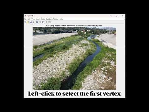
Select the vertices of the desired polygonal mask in the input and reference photos. A video guide for mask selection is below.
-
The aligned image will be saved as
[photo file name]_registered.[registration file type]. -
Apply
stereoCam_reconstructSceneto the two registered input photos to create your 3D reconstruction.
The photos’ masks will be saved as [photo file name]_mask.mat. If these same photos are reused, these .mat files can be loaded in as the reference_photo_mask and unaligned_photo_mask inputs to stereoCam_alignImages. An example is provided in Option 5 of stereoCam_main.m..
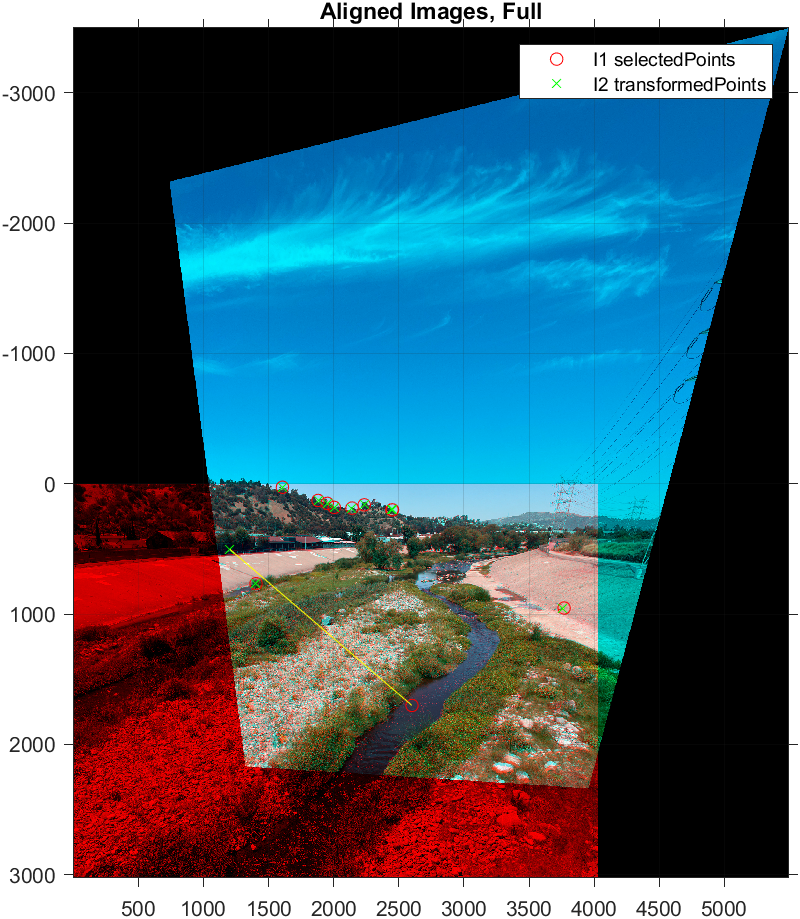
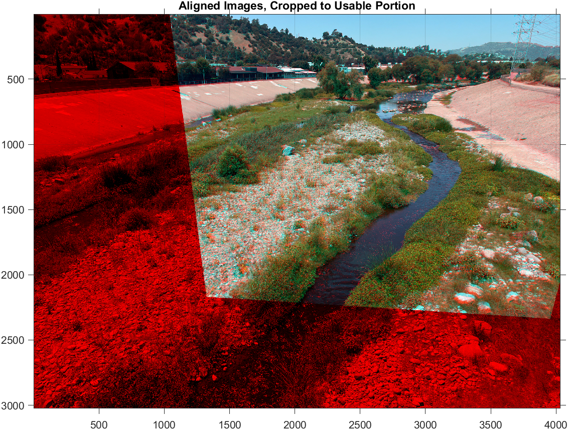
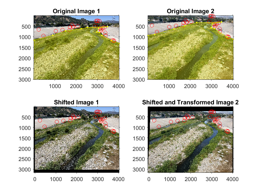
The figure below shows the process of aligning images when a mask is used.
Once alignment is completed for a pair of input images, one from each holder of the phone stand, a 3D reconstruction can be generated using stereoCam_reconstructScene! Make sure to input the photos as shown below:
The 3D reconstructions are generated using the stereoParams calibration file stored in calibrated_stereoParams.mat.
The stereoCam_reconstructScene function uses MATLAB’s built-in reconstructScene, which generates multiple figures so you can monitor the progress of the reconstruction:
The two camera angles share enough information to generate a 3D reconstruction of this region of the river. The C1 angle is shown in red, and the C2 angle is shown in cyan.
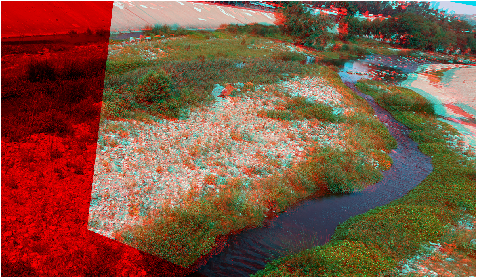
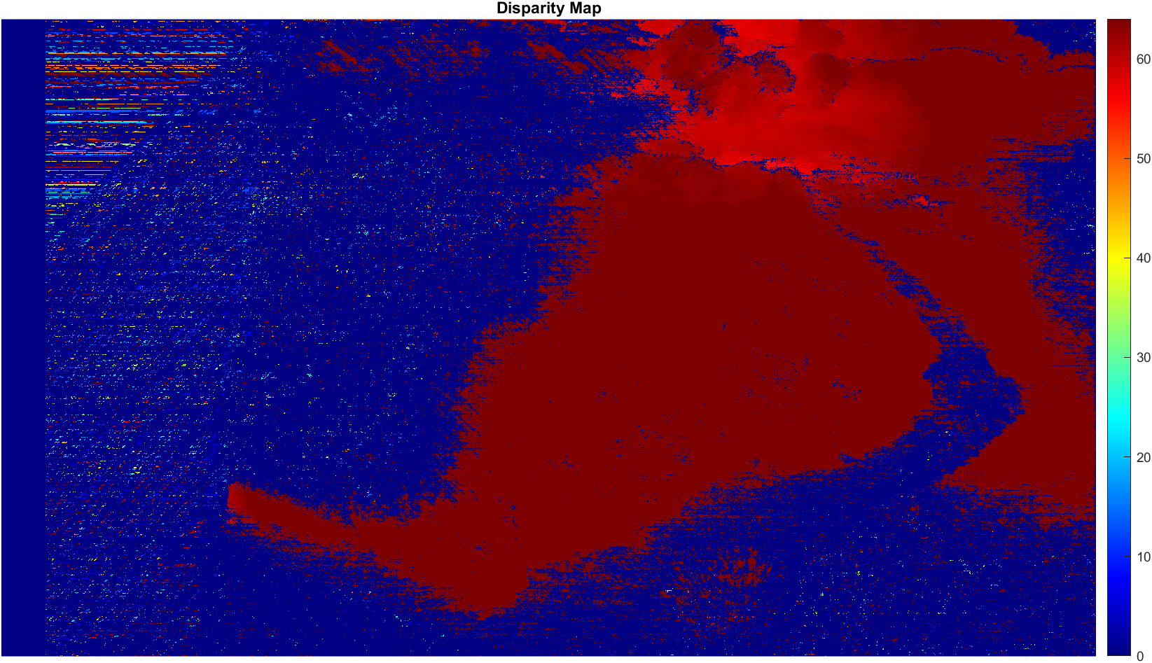
The disparity map shows the apparent distance travelled by a particular object visible in both images. The closer an object is to the cameras, the greater the disparity, and the redder they will appear in the disparity map.
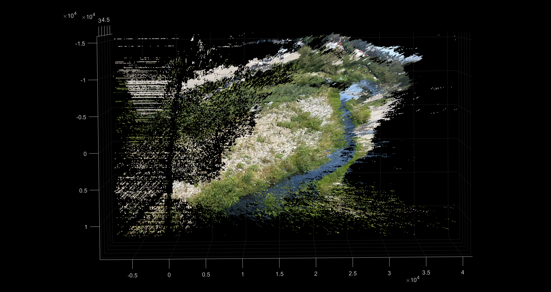
Below is a photo and video of the final 3D reconstruction!
[1] Flowers, V., Frutos, C., Mackenzie, A. S., Fanning, R., & Fraser, E. E. (2023). Snap Decisions: Assessing Participation and Data Quality in a Citizen Science Program Using Repeat Photography. Citizen Science: Theory and Practice, 8(1). https://doi.org/10.5334/CSTP.558
[2] Lowe, D. G. (2004). Distinctive image features from scale-invariant keypoints. International Journal of Computer Vision, 60(2), 91–110. https://doi.org/10.1023/b:visi.0000029664.99615.94
[3] Bay, H., Tuytelaars, T., & Van Gool, L. (2006). Surf: Speeded up robust features. Lecture Notes in Computer Science, 404–417. https://doi.org/10.1007/11744023_32
[4] Leutenegger, S., Chli, M., & Siegwart, R. Y. (2011). Brisk: Binary robust invariant scalable keypoints. 2011 International Conference on Computer Vision. https://doi.org/10.1109/iccv.2011.6126542
[5] Tareen, S. A., & Saleem, Z. (2018). A comparative analysis of SIFT, surf, Kaze, AKAZE, Orb, and brisk. 2018 International Conference on Computing, Mathematics and Engineering Technologies (iCoMET). https://doi.org/10.1109/icomet.2018.8346440
[7] Graham, E. A., Henderson, S., & Schloss, A. (2011). Using mobile phones to engage citizen scientists in research. Eos, 92(38), 313–315. https://doi.org/10.1029/2011EO380002
[8] Harley, M. D., & Kinsela, M. A. (2022). CoastSnap: A global citizen science program to monitor changing coastlines. Continental Shelf Research, 245. https://doi.org/10.1016/j.csr.2022.104796
[9] Pagano, A., Hill, D., Valentini, N., & Spasiano, A. (n.d.). Testing the theoretical principles of citizen science in monitoring stream water levels through photo-trap frames.
[10] Rittgers, G., ezfn, & Dima. (2015, August 15). Matlab stereo camera calibration scene reconstruction error. Stack Overflow. https://stackoverflow.com/questions/32026385/matlab-stereo-camera-calibration-scene-reconstruction-error
[11] schurist, & fdermishin. (2020, December 22). Stereo calibration and 3D reconstruction issue. Stack Overflow. https://stackoverflow.com/questions/65410580/stereo-calibration-and-3d-reconstruction-issue?noredirect=1&lq=1
[12] Scott, S. L., Venter, Z. S., Petersen, H., Jack, S. L., Navarro, R. A., & Hoffman, M. T. (2021). Documenting changing landscapes with rePhotoSA: A repeat photography and citizen science project in southern Africa. In Ecological Informatics (Vol. 64). Elsevier B.V. https://doi.org/10.1016/j.ecoinf.2021.101390